Rotor vijčanog kompresora je ključni sastavni dio cijelog sustava kompresije, a njegovo stanje izravno određuje učinkovitost opreme u proizvodnji zraka te vijek trajanja. U ovom članku detaljno se objašnjavaju uobičajeni kvarovi rotora, njihovi uzroci te najvažnije mjere prevencije i kontrole, kako bi se osoblju za održavanje omogućilo brzo otklanjanje i rješavanje problema.
I. Sastavni dijelovi rotora
Sklop rotora temelji se na pogonskom rotoru (muški rotor) i gonjenom rotoru (ženski rotor), uz dodatne ključne komponente kao što su glavni ležajevi, aksijalni ležajevi, poklopci ležajeva, balansni klipovi i rukave balansnog klipa.
II. Uobičajeni kvarovi rotora
1. Normalno mehaničko trošenje i starenje
- Trošenje vanjskih promjera zubnih traka muškog/ženskog rotora
- Prirodno trošenje cilindara rotora
2. Mehanička oštećenja uzrokovana ljudskom pogreškom
- Ogari na vanjskim promjerima zubnih traka muških/ženskih rotora
- Ogari na unutarnjim stjenkama cilindara rotora
- Ogari na stranama poklopaca ulaznog/izlaznog kraja rotora
- Trošenje ležajeva na ulaznom/izlaznom kraju i unutarnjih krugova poklopaca ležajeva
Trošenje vratila na promjerima u područjima postavljanja ležajeva rotora
Deformacija krajeva vratila rotora
3. Područja visokog rizika za ogrebotine/zakočenje komponenti
Ogrebotine i zakočenje (zakusanje) na spojnim površinama muških/ženskih rotora
Trenje vanjskog promjera rotora o unutarnje stjenke kućišta
Trenje izlazne plohe rotora i kućišta izlaznog ležaja
Hab i zakošnjavanje između vratila ulaznog dijela rotora i ležajnog kućišta osovine
Hab i zakošnjavanje ležajeva izlaznog dijela rotora s provrtima ležajnog kućišta za ispuštanje
III. Osnovni uzroci kvarova rotora
Nepravilno održavanje zraka i podmazivanja Neuzamjena zračnih filtera prema rasporedu dovodi do prekomjerne količine prašine u usisavanom zraku, zbog čega one pridođu u kompresijsku komoru i uzrokuju ozbiljan hab rotora. Slobodno miješanje različitih marki podmazivača može uzrokovati stvaranje ugljičnih naslaga i sluzi u ulju, što dodatno ubrzava habanje rotora.
Nepridržavanje propisa pri odabiru/izmjeni podmazivača: Korištenje ulje za kompresor vrsta koje ne zadovoljavaju specifikacije opreme ili zanemarivanje planiranih zamjena ulja dopušta prekomjernu količinu nečistoća u ulju, što izravno uzrokuje ogrebotine na preciznim dijelovima poput rotora i cilindričnih cijevi.
Nepravilni radni parametri pokreću kaskadne kvarove. Previše niske temperature pražnjenja tijekom rada povećavaju sadržaj vlage u uljno-plinskoj smjesi, što s vremenom dovodi do emulzifikacije ulja. Emulzificirano mazivo ne može dovoljno podmazivati ležajeve na ulaznom/izlaznom kraju, što uzrokuje pregrijavanje i oštećenje u uvjetima visoke brzine i velikog opterećenja. Konačno, to rezultira neravnotežom rotorske osovine, deformacijom ili zaglavljivanjem.
Kvarovi pogonskih komponenti
Problem poput nepravilnog zazora pri spajanju zupčanika na pogonskom kraju ili kvar ključnog spoja može uzrokovati neravnomjernu raspodjelu naprezanja na kraju pogonske osovine, što dovodi do deformacije kraja osovine.
Defekti kvalitete ležajeva
Korištenje nepodudarnih komponenata ležajeva povećava rizik od nepravilnog kvara ležaja, što posredno izaziva ekscentričnost rotora i habanje.
Nedovoljna točnost obrade i sklopa: Osječci vratila za usisavanje i tlačenje rotora oslonjeni su na ležajeve u kućištu kompresora i kućištu tlačnog ležaja, respektivno. Ako koaksijalnost između kućišta, ležajnog kućišta i rotora ne zadovoljava projektne standarde (koji moraju biti kontrolirani unutar 0,01–0,02 mm), to može lako uzrokovati trenje ili zaglavljivanje između rotora, između rotora i kućišta ili s drugim komponentama.
Akumulacija konstrukcijskih i proizvodnih pogrešaka Unutarnji dijelovi unutar kompresijske komore imaju precizne dinamičke dosjede, s zazorima izmjeranim u tisućinkama inča ili milimetara. Ako je projektirani zazor preuzak, uz dodatne tolerancije pri proizvodnji, znatno se povećava vjerojatnost ogrebotina na rotoru ili njegovog zaglavljivanja. Pod normalnim uvjetima rada, zazor između rotora i kućišta iznosi otprilike 0,1 mm, dok zazor između izlaznog lica rotora i ležajnog kućišta na izlazu iznosi od 0,05 do 0,1 mm.
Nepravilni postupci demontaže i montaže Tijekom demontaže, ležaj i vratilo rotora imaju čvrsti dosjed. Prevelika sila prilikom skidanja može uzrokovati deformaciju dijelova, smanjujući njihovu prirodnu koaksijalnost. Nakon montaže jedinice, ako se ne provjeri ukupna koaksijalnost sklopljenih dijelova, to može dovesti do habanja dijelova ili zaglavljivanja rotora ako se uređaj pokrene u uvjetima izvan dopuštenih tolerancija.
Sažetak: Većina navedenih kvarova rotora u zavojnim kompresorima usko je povezana s ljudskom operacijom, održavanjem i postupcima sklopa. Tijekom redovitog održavanja, strogo pridržavanje postupaka rada i održavanja opreme te provedba redovitih mjera održavanja mogu učinkovito spriječiti takve kvarove.
 Najnovije vijesti
2026-05-18
2026-03-03
2026-01-31
2026-01-29
2026-01-22
2026-01-15
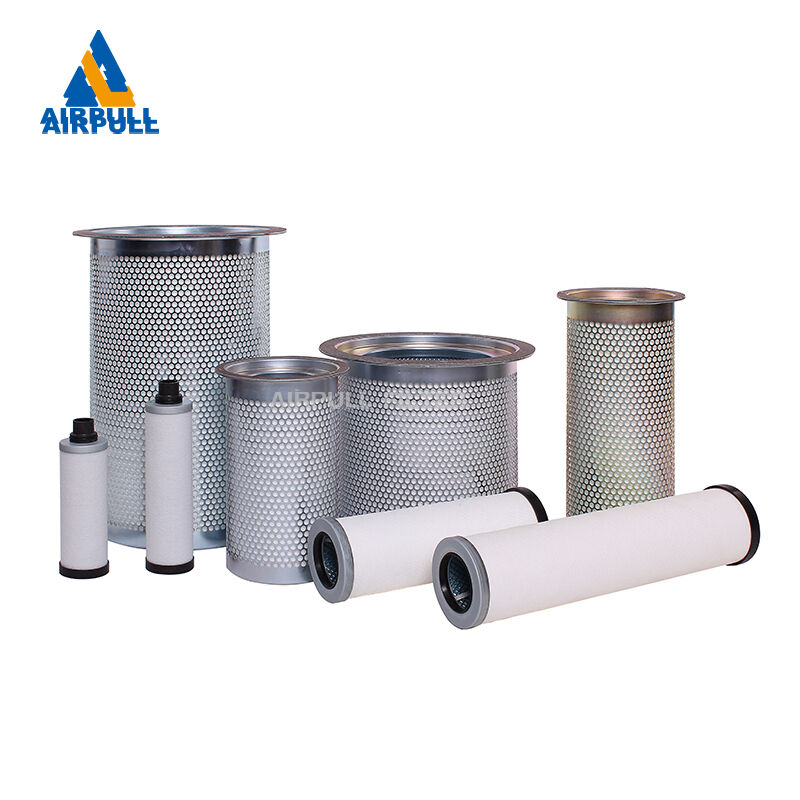
XINXIANG AIRPULL FILTER CO.,LTD nudi visokoučinkovite filtre za kompresorski zrak, separatore ulja i plina te industrijske sustave filtracije. S više od 30 godina iskustva i 33 patenta, nudimo pouzdana rješenja za energetiku, naftnu i kemijsku industriju. Dostava u više od 50 zemalja diljem svijeta.
Nacionalni industrijski park za kemijsko i fizičko snabdijevanje energijom, ulica Newqi, četvrt Muoye, grad Xinxiang, provincija Henan
Copyright © 2026 XINXIANG AIRPULL FILTER CO., LTD sva prava rezervirana Pravila o privatnosti