 ×
×

Oil-injected screw air compressors are widely used in industrial production due to their highly efficient and stable operation. However, in actual operating conditions, frequent loading/unloading failures often occur, leading to issues such as freque...
Contact Us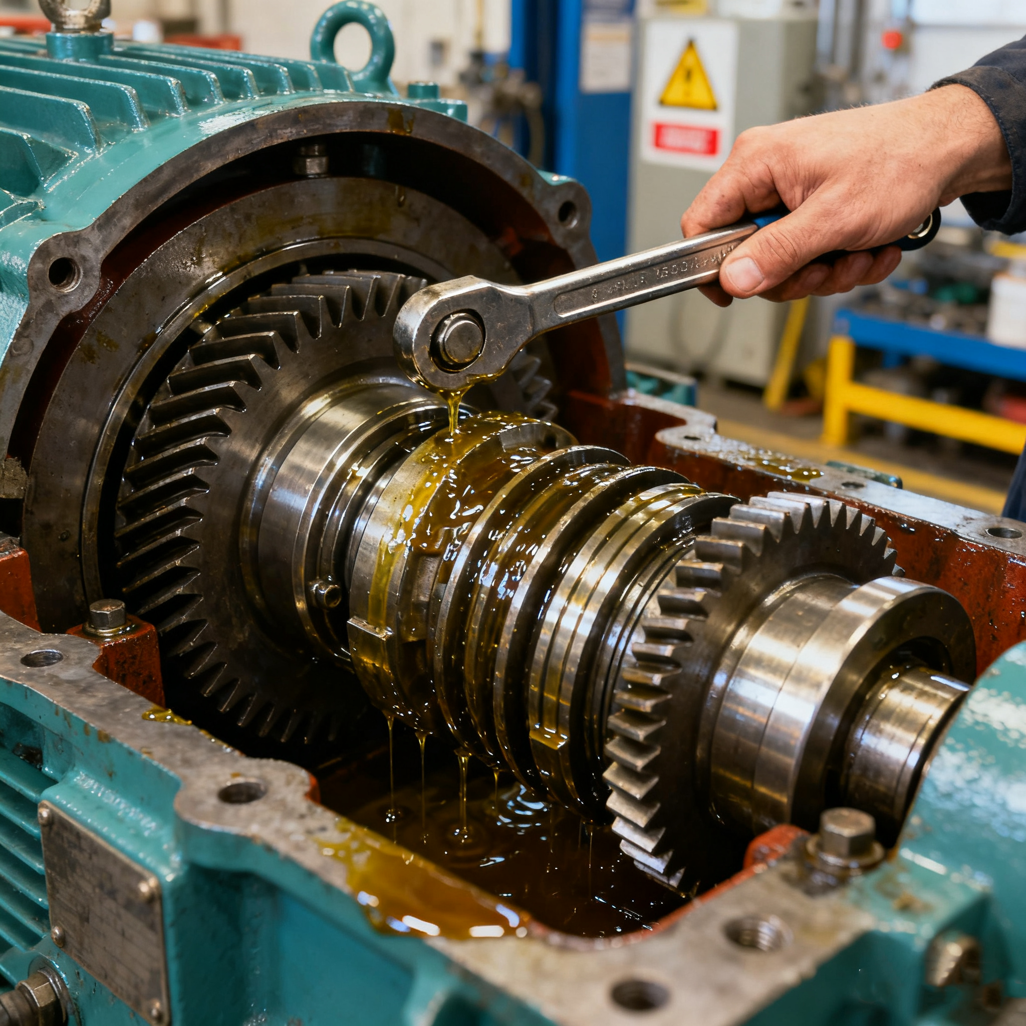
Oil-injected screw air compressors are widely used in industrial production due to their highly efficient and stable operation. However, in actual operating conditions, frequent loading/unloading failures often occur, leading to issues such as frequent equipment start-stops and fluctuating air supply pressure. These problems not only disrupt production continuity but also accelerate equipment aging and increase energy consumption losses, necessitating systematic analysis and targeted solutions.
I. Analysis of the Load/Unload System Operating Principle
(1) Dynamic Loading Mechanism
When system pressure drops below the preset lower limit, pressure switches or high-precision pressure sensors rapidly capture the pressure signal, triggering the control system to issue commands that open the intake valve. The compressor rotors then initiate the air compression process. The compressed air undergoes oil-gas separation, cooling, and other treatment processes before being delivered to the air consumption end, precisely matching production air demand.
(2) Intelligent Unloading Logic
Once system pressure reaches the set upper threshold, pressure sensors instantly relay feedback signals. The control system promptly commands the intake valve to close. The air compressor then transitions to no-load operation mode—the rotor continues rotating while the air intake pathway is completely blocked, ceasing compressed air production to effectively reduce operational energy consumption.
(III) Pressure Closed-Loop Control System
By flexibly setting upper and lower threshold limits for pressure switches or sensors, the system precisely defines the pressure range for loading and unloading. Some high-end models incorporate PID dynamic adjustment functionality, enabling real-time pressure compensation. This minimizes fluctuations in supply pressure, ensuring stable air usage.
II. Core Causes of Load/Unload Failures
(1) Sensor Component Failure Risks
Aging and Accuracy Drift: Phenomena like oxidation of pressure switch contacts or sensor chip drift can distort pressure signal acquisition. A certain automotive manufacturer experienced a zero-point drift failure in pressure sensors, causing compressors to unload prematurely before reaching the lower limit, directly resulting in insufficient air supply to the production line.
Environmental Interference: High temperatures and humidity accelerate sensor degradation. Dust and oil contamination on sensing surfaces directly reduce sensitivity, causing signal transmission delays or misjudgments.
(2) Intake Valve Failure Risks
Mechanical Sticking Issues: Intake valve pistons may become stuck due to carbon buildup, debris blockage, or fatigue failure of the return spring, preventing smooth valve operation. In the textile and dyeing industry, such failures account for 35% of all air compressor loading/unloading malfunctions, making them a primary cause of interrupted equipment operation.
Electromagnetic Control Failure: Damage to the electromagnetic coil insulation, loose or oxidized terminal connections can prevent the solenoid valve from accurately responding to control signals. This causes the air compressor to remain in a continuous loading or permanent unloading state, losing its pressure regulation capability.
(III) Control System Failure Pathways
Hardware Failures: Issues such as lost PLC module programs, poor solder joints on control circuit boards, or oxidized terminal connections can disrupt the transmission of control commands. A certain electronics factory experienced severe pressure fluctuations and reduced product yield due to a PLC output port failure that caused the intake valve to malfunction.
Software Logic Defects: Improper parameter configuration in control programs or flaws in loading/unloading control algorithms can lead to inaccurate pressure threshold judgments, resulting in misaligned loading/unloading timing.
(IV) Pipeline Leakage Losses
Sealing Failure: Aging flange gaskets, loose threaded joints, or damaged seals can cause persistent compressed air leakage. Industry statistics indicate a 1mm² leak hole wastes approximately 15,000 cubic meters of compressed air annually, forcing air compressors to frequently cycle on to compensate for pressure loss.
Pipe Corrosion Perforation: Piping subjected to long-term operation is susceptible to corrosion perforation due to media erosion and gas flow scouring, particularly pronounced in highly corrosive environments like chemical processing and metallurgy.
(5) Mechanical Component Wear Effects
Critical components like intake valve stems and pressure switch microswitch mechanisms experience increased clearance, surface wear, and seal failure after prolonged high-frequency operation. This leads to delayed loading/unloading responses, incomplete actuation, and even valve sticking.
III. Fault Diagnosis and Precision Solutions
(1) Precision Maintenance of Sensing Systems
Regular Calibration: Utilize high-precision pressure calibrators to perform quarterly zero-point and range calibration on pressure switches and sensors, ensuring measurement errors remain within ±1% to guarantee signal acquisition accuracy.
Protection Upgrades: Install dust-proof and moisture-proof covers on sensing elements and regularly clean sensing surfaces. In highly corrosive environments, apply anti-corrosion coatings to component surfaces to extend service life.
(II) Intake Valve Restoration and Performance Recovery
Disassembly Inspection: Dismantle intake valve assemblies. Thoroughly remove carbon deposits, oil residues, and contaminants using specialized cleaning agents. Inspect valve seat sealing surfaces and spool wear. Grind and repair minor wear areas; replace components for severe wear.
Performance Validation: After reassembly, test valve sealing performance on a pneumatic leak test bench. Simulate actual operating conditions using dynamic simulation equipment to verify valve response time and sealing precision meet specifications.
(III) Control System Deep Diagnosis and Optimization
Hardware Inspection: Utilize professional tools like multimeters and oscilloscopes to inspect PLC input/output signals and circuit board voltage/current parameters. Locate loose or damaged components for immediate replacement to ensure stable hardware loops.
Program Optimization: Control program logic is revalidated. Simulation tests verify the rationality of loading/unloading control algorithms, correct parameter configuration deviations, and update the program to the latest stable version.
(IV) Precision Pipeline Leak Remediation
Precision Leak Detection: Ultrasonic leak detectors scan the entire pipeline network with millimeter-level accuracy for leak localization. Suspected leak areas are marked with leak detection fluid for secondary confirmation via bubble formation observation.
Tiered Repair: Minor leaks sealed with specialized rapid-setting sealant; severely damaged pipes replaced outright. Threaded connections coated with anti-loosening adhesive; flange interfaces fitted with high-temperature/aging-resistant gaskets to enhance sealing performance.
(5) Mechanical Component Renewal and Maintenance
Wear Assessment: Measure critical components like valve stems and plugs using precision tools such as micrometers and calipers. Replace parts exceeding wear limits promptly to ensure clearance meets technical specifications.
Lubrication Optimization: Apply high-temperature grease suited for operating conditions to uniformly lubricate moving mechanical parts. This reduces friction resistance, ensuring smooth and flexible component operation.
XINXIANG AIRPULL FILTER CO.,LTD provides high-efficiency air compressor filters, oil-gas separators, and industrial filtration systems. With 30+ years of expertise and 33 patents, we deliver reliable solutions for power, petroleum, and chemical industries. Global shipping to 50+ countries.
National Chemical and Physical Power Supply Industrial Park, Newqi Street, Muoye District, Xinxiang City, Henan Province
Copyright © 2026 XINXIANG AIRPULL FILTER CO.,LTD All rights reserved Privacy Policy


