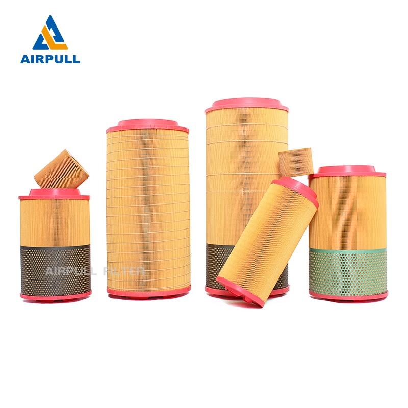
Основни радни делови завртњастог компресора чине пар међусобно усклађених спиралних мушких и женских ротора у цилиндру. Оба ротора имају више удубљених зубаца и током рада се обрћу на високим бројевима окретаја у супротним правцима. Размак између ротора и између ротора и унутрашњег зида кућишта износи само 5 до 10 хиљадитих инча (0,05 до 0,10 милиметара), чиме се осигурава заптивност процеса компресије гаса.
Što se tiče pogonskog sistema, glavni rotor (takođe poznat kao muški ili konveksni rotor) obično se pokreće električnim motorom (iako postoje verzije sa pogonom motora u nekim primenama). Prenos snage na sekundarni rotor (takođe poznat kao ženski ili konkavni rotor) ostvaruje se na dva osnovna načina: fleksibilnim pogonom preko filma ulja koji nastaje ubrizgavanjem ulja, ili krutim prenosom preko sinhronih zupčanika na krajevima oba rotora. Oba metoda pogona osiguravaju da tokom rada rotora ne dođe do direktnog metalnog dodira (teoretski), čime se efikasno smanjuje habanje i poboljšava radna stabilnost.
Količina ispuštanja (protok) i pritisak kompresora u velikoj meri zavise od konstruktivnih parametara rotora: duži rotori povećavaju sposobnost stvaranja pritiska tokom takta kompresije, što rezultira većim pritiskom ispuštanja; veći prečnik rotora povećava zapreminu gasa po ciklusu usisavanja, što dovodi do veće količine ispuštanja.
Радни циклус прати низ „усисавање – компресија – испуштање“, детаљно описан на следећи начин: Када простор између завојница ротора стигне до положаја усисног отвора, његова запремина се постепено повећава. Околни гас усисава се под дејством разлике притиска и испуњава простор. Док ротор настави да се окреће, простор испуњен гасом затвара се зидом кућишта, формирајући независну комору за компресију. У том тренутку, под високим притиском убризгава се подмазивање у комору, истовремено обављајући три функције: заптивање, хлађење и подмазивање. Наставак окретања ротора узрокује стално смањење запремине компресионе коморе, постепено компрујући мешавину уља и гаса (мешавину подмазивања и гаса) унутар коморе, што резултира трајним повећањем притиска. Када се компресиона комора окрене и поравна са отвором за испуштање, високопритисна мешавина уља и гаса исцрпљује се из компресора под притиском, чиме се довршава пун радни циклус.
Стабилан рад ротора омогућен је системом лежајева смањених трења: лежајеви су утврђени и позиционирани преко завршних капи на крајевима вратила. На улазном крају обично се користе котрљајући лежајеви, који првенствено прелазе радијална оптерећења; на излазном крају налази се пар супротних конусних котрљајућих лежајева. Ови лежајеви имају двоструку функцију: делују као осни лежајеви како би нивелисали осно тегло настало радом ротора, али истовремено прелазе и радијална оптерећења. Уз то, обезбеђују минимални осни зазор потребан за кретање ротора, чиме се осигурава прецизан рад у оквиру задатих граница.
Притом, док ротор стално ротира, сваки пар усклађених зубних жлебова редом понавља процес „усисавања—компресије—испустања“. Радни циклуси више зубних жлебова се међусобно повезују и наизменично се настављају, омогућавајући компресору сталан и стабилан излаз гаса.
 Топла вест
2026-05-18
2026-03-03
2026-01-31
2026-01-29
2026-01-22
2026-01-15
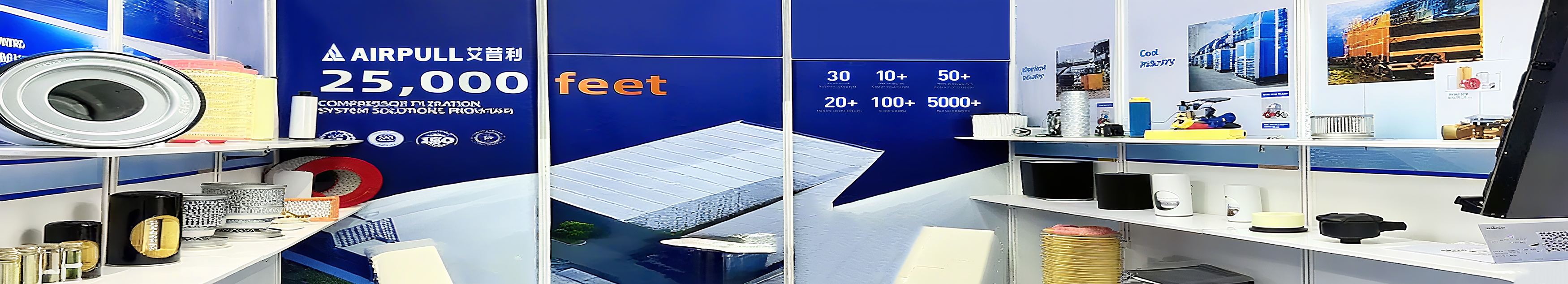
Ксинсианг Аирпул филтер ЦО., ЛТД пружа високоефикасне филтере за ваздушне компресоре, сепараторе нафте и гаса и индустријске филтрационе системе. Са више од 30 година стручности и 33 патента, пружамо поуздана решења за енергетску, нафтну и хемијску индустрију. Глобална испорука у више од 50 земаља.
Национални индустријски парк за снабдевање хемијским и физичким енергијом, улица Њуцхи, Муоје округ, град Синксианг, провинција Хенан
Copyright © 2026 Ксинцзянг Аирпул филтер ЦО, ЛТД Сва права задржана Политике приватности